Godot plugin
Godot Plugin Integration(Windows & ubuntu22)
This document provides detailed instructions on how to integrate and utilize the Determ Flowbit Server library within a Godot Engine project.
Determ Flowbit Server Integration with Godot Engine
Godot projects rely on the gdextension library to integrate the Determ Flowbit Server library. You have two options to integrate the Determ Flowbit Server library with Godot Engine.
Use the exported plugin located in the
flowbitserver_godot/example/exported_pluginfolder. This is the easier option, and you don't need to build the gdextension library. You can directly use the plugin in a new project. However, if you want to develop your project based on the example project, you need to build the gdextension library from the source code.Build the gdextension library from the source code. This is a more complex option, and you need to build the gdextension library from the source code first to generate the gdextension library file (dll or so), which is used by the Godot engine.
Windows 11
Install the required dependencies(Windows)
Requirements Specific to the Platform: Before integrating the Determ Flowbit Server library with Godot Engine, ensure the following requirements are met for your Godot project. The Determ Flowbit Server plugin works for Godot Engine projects on Windows Please follow the instructions below to install the required dependencies for your platform.
Development Tools
Dependencies
Install the above dependencies with default settings.
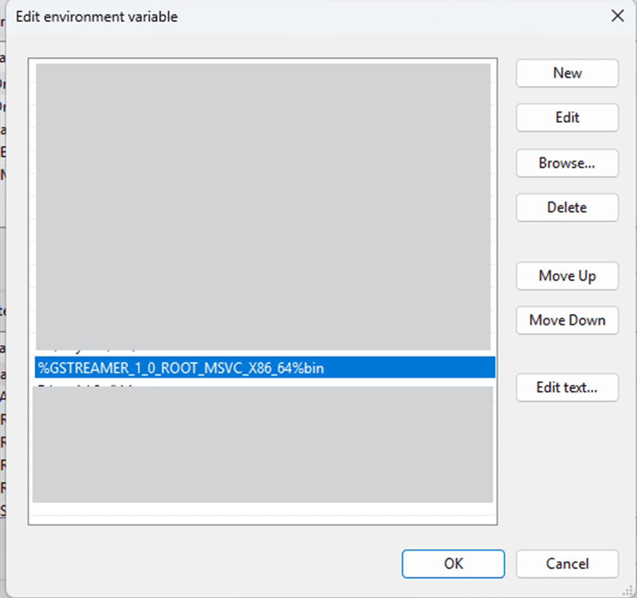
For GStreamer, add the GStreamer bin path to the system environment variable Path. Restart the system for the changes to take effect.
Plugin Installation(Windows)
This describes how to obtain and install the Determ Flowbit Server Godot plugin into your project.
Download the Determ Flowbit Server Godot plugin from the Determ Flowbit Releases page
Unzip the plugin to a target path.
The plugin has the following structure for Windows.
Use exported plugin in a new project(Windows)
The plugin ia already exported in the flowbitserver_godot/example/exported_plugin folder. This guide will show you how to use the exported plugin in a new project. In this way, you can use the plugin without building the lowlevel gdextension.
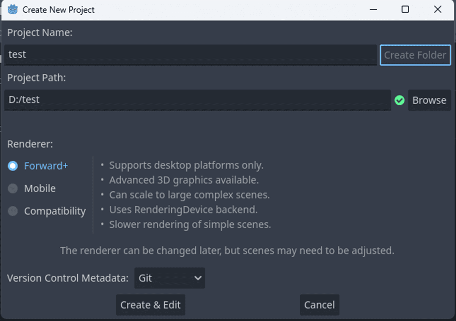
Create a new project and open the empty project.
Exit the project.
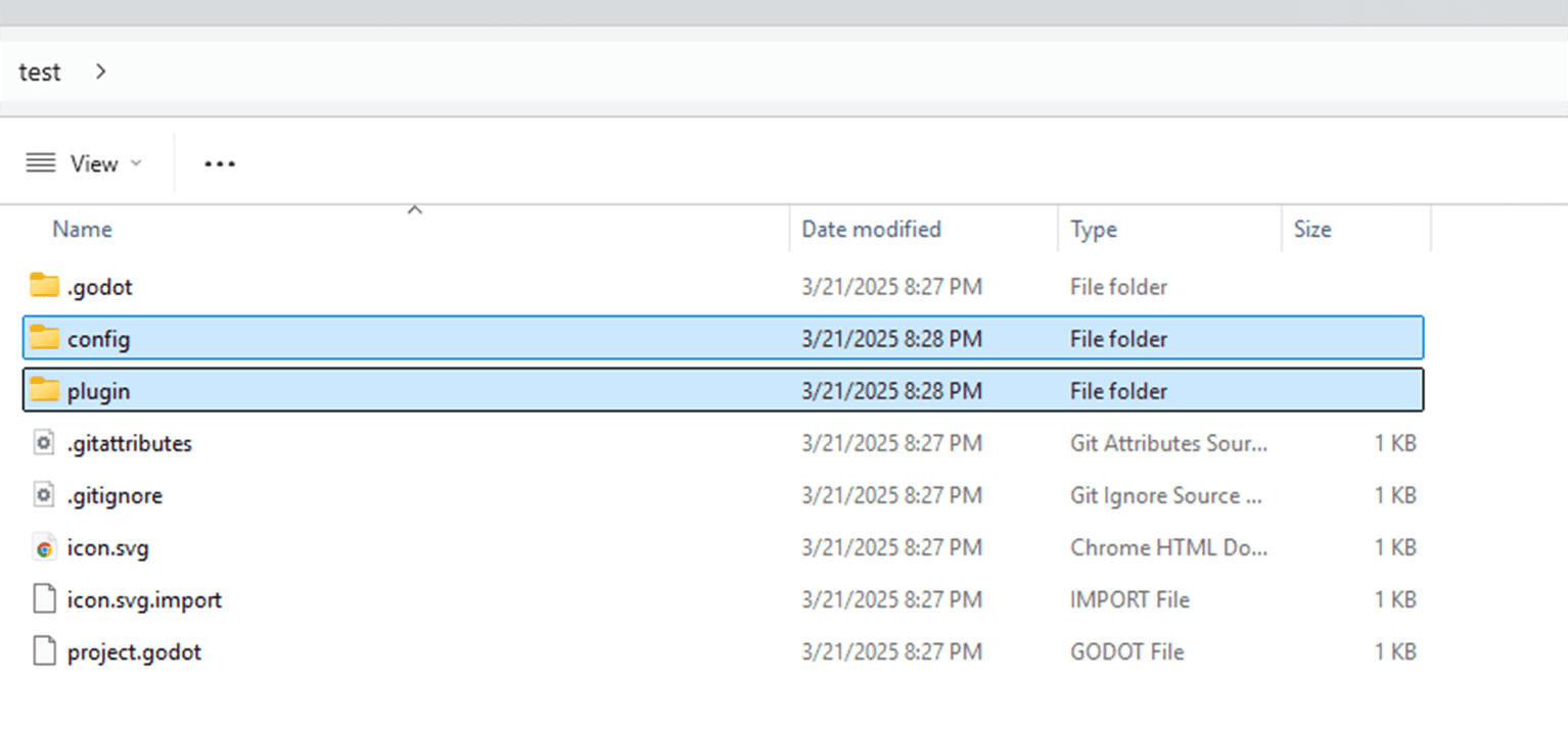
Copy the
exported_plugin/configfolder to the new project folder<project_folder>/config.Copy the
exported_plugin/pluginfolder to the new project folder<project_folder>/plugin.
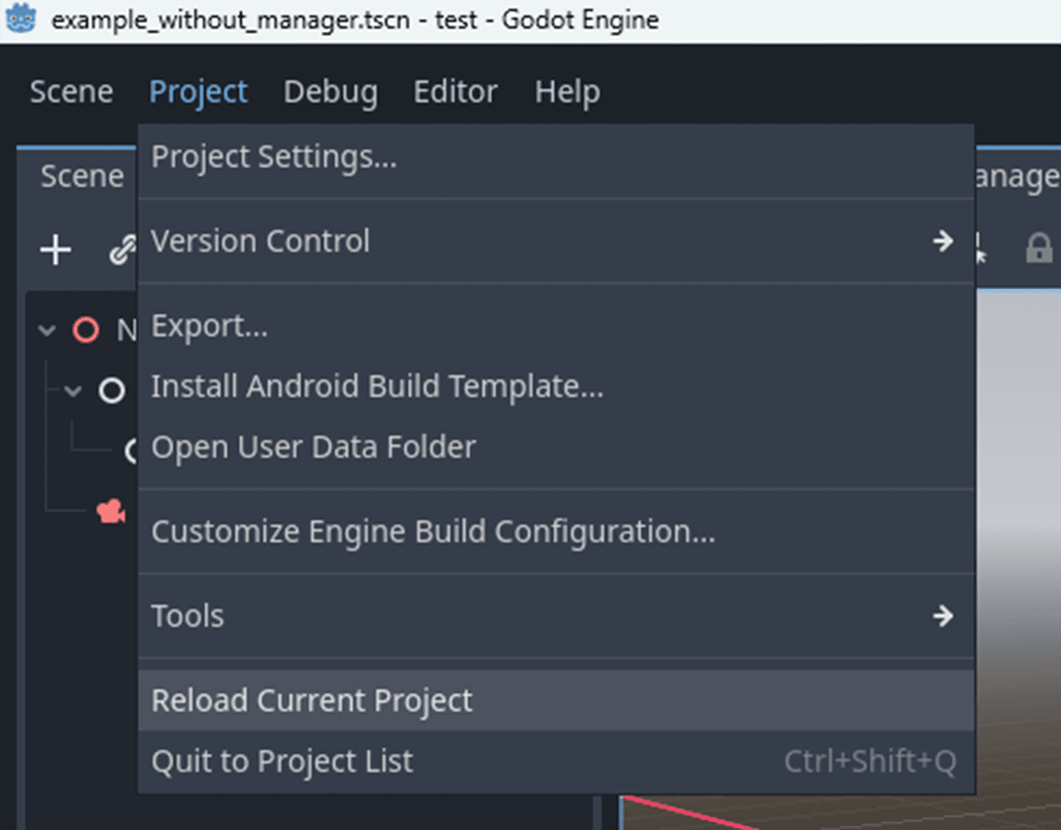
Open the new project again.
Click
Project->Reload current prokectto reload the project.
Double click the scene file
res://plugin/flowbitserver_godot/example_with_manager.tscnto open the scene
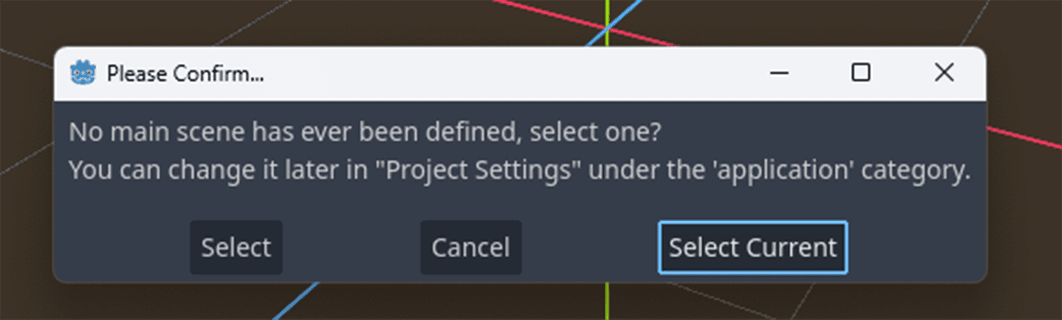
Press F5 and select current as the main scene to start.

Build and run the example project(Windows)
Structure of the installed example project
The example project is located in the flowbitserver_godot/example/ folder.
Build the gdextension of the example project
Open Cmake GUI and set the source code path to
example\gdextensionfolder, and set the build path to the build folder to theexample\gdextension/buildfolder.Press
Configure, selectVisual Studio 17 2022as the generator, and pressFinish.Set the
flowbitserver_godot_folderto the plugin folder.Press
Generateto generate the Visual Studio solution file and build thedebugandreleaseversion of the gdextension.
The
flowbitviewerplugind.dllfile for debug version will be copied to theexample\godot\plugin\flowbitserver_godot\bin\debugfolder, andflowbitviewerplugin.dllfile for release version will be copied to theexample\godot\plugin\flowbitserver_godot\bin\releasefolder. Other dependency dll files will be copied to the same folder.
The config files are also copied to the
example\godot\configfolder after the build.
Open the godot project
example\godotfrom the project manager.Open the
example_with_manager.tscnscene and pressRunto run the project.
Ubuntu22/Ubuntu24
Install the required dependencies(Linux)
Requirements Specific to the Platform: Before integrating the Determ Flowbit Server library with Godot Engine, ensure the following requirements are met for your Godot project. The Determ Flowbit Server plugin works for Godot Engine projects on Linux (Ubuntu 22/24). Please follow the instructions below to install the required dependencies for your platform.
1. Install Nvidia GPU driver
NvidiaUbuntu — NVIDIA Driver Installation Guide
2. Install CUDA (V12.8)
NvidiaCUDA Toolkit 12.8 Downloads
Check if CUDA is installed by running: nvcc --version
3. Install GStreamer
Ubuntu 22.04:
Install gstreamer v1.20.3 and required plugins by running the following command in your terminal:
Ubuntu 24.04:
Install gstreamer v1.24.2 and required plugins by running the following command in your terminal:
Check the gstreamer version by running:
Check for nvcodec support:
If nothing is printed, try clearing the cache and re-running the command:
Add pkg_config to Path
4. Install other libs
Plugin Installation(Ubuntu22/24)
This describes how to obtain and install the Determ Flowbit Server Godot plugin into your project.
Download the Determ Flowbit Server Godot plugin from the Determ Flowbit Releases page.
Ubuntu22:
wget https://file.determtech.com/software/flowbit_server/plugins/godot/flowbitserver_godotplugin_1.4.1_ubuntu22.zip
Ubuntu24:
wget https://file.determtech.com/software/flowbit_server/plugins/godot/flowbitserver_godotplugin_1.4.1_ubuntu24.zip
Unzip the plugin to a target path.
The plugin has the following structure for Windows and Linux.
Use exported plugin in a new project(Linux)
The plugin ia already exported in the flowbitserver_godot/example/exported_plugin folder. This guide will show you how to use the exported plugin in a new project. With this method, you can use the plugin without building the low-level gdextension.
Create a new project and open the empty project.
Exit the project.
Copy the
exported_plugin/configfolder to the new project folder<project_folder>/config.
Copy the
exported_plugin/pluginfolder to the new project folder<project_folder>/plugin.
Open the new project again.
Click
Project->Reload current prokectto reload the project.
Double click the scene file
res://plugin/flowbitserver_godot/example_with_manager.tscnto open the scene
Press F5 and select current as the main scene to start.
Build and run the example project(Linux)
Structure of the installed example project
The example project is located in the flowbitserver_godot/example/ folder.
Build the gdextension of the example project
Open
example/gdextensionfolder in terminal and run the following command to build the gdextension. Set theflowbitserver_godot_folderto the plugin folder.
The
libflowbitviewerplugind.sofile for debug version will be copied to theexample/godot/plugin/flowbitserver_godot/bin/debugfolder, andlibflowbitviewerplugin.sofile for release version will be copied to theexample/godot/plugin/flowbitserver_godot/bin/releasefolder. Other dependency dll files will be copied to the same folder.
The config files are also copied to the
example/godot/configfolder after the build.
Open the godot project
example/godotfrom the project manager.Open the
example_with_manager.tscnscene and pressRunto run the project.
Example project walkthrough and development
Applies to both Windows and Linux
Edit the .gdextension file
The default .gdextension file is flowbitserver_godot/example/godot/plugin/flowbitserver_godot/gdextension.gdextension . You can edit this file to change the default values.
In this file:
entry_symbolis the entry symbol of the gdextension library. It must be the same to the entry symbol inregister_types.cpp.compatibility_minimumis the minimum version of the Godot engine that the gdextension supports.windows.debug.x86_64is the path to the gdextension debug version library.windows.release.x86_64is the path to the gdextension release version library.linux.debug.x86_64is the path to the gdextension debug version library.linux.release.x86_64is the path to the gdextension release version library.dependenciesare the dependency dll files for the gdextension. The key is the path to the dependency dll file, and the value is the folder where the dependency dll file is copied on exporting the project. For Linux, the dependency so files are not needed.
Config the example Godot project
Nodes can be used in the editor
Node name | Description |
FlowbitViewerCore | The core node to control the gdextension. It gets the config and data folder paths first, then starts the file system, system service, and logging service in the constructor. |
FlowbitViewerDeviceManagerPanel | Controls the device manager service to detect all network devices. Available devices are listed in the UI and refreshed in real-time. It should work with the DeviceConfigNode to show all devices and their configurations. |
DeviceConfigNode | Packs each device's configuration info and shows it in the UI. Users can connect/disconnect devices, download device profiles, and configure the device. |
FlowbitViewerEnginePanel | Shows the engine config in the UI. Users can configure the engine config by editing, saving, and reloading the config. It should work with the CodeEdit node to show the engine config. |
FlowbitViewerLivescenePanel | Controls streaming and recording tasks. It can work with the 2D image window node to show the 2D images. |
FlowbitViewerPlaybackPanel | Lists all playback events in the UI with PlaybackEventNode. Users can play, pause, stop, and seek the playback events. It can work with the 2D image window node to show the 2D images. |
PlaybackEventNode | Packs each playback event's info and shows it in the UI. It should work with the PlaybackEventNode to show each playback event. |
RenderingNode | Used to show the point cloud in the UI. It should work with the shader material file to render the point cloud. Each device has a rendering node to show the point cloud, and the rendering node is created dynamically on starting the rendering task by the FlowbitViewerLivescenePanel node or FlowbitViewerPlaybackPanel node. Users should not create the rendering node manually. |
FlowbitViewerDialog | Packs the dialog info and shows it in the UI. It connects to signals from the SignalEmitter node on initializing the dialog. Users can show accept, confirm, and notify dialog types by emitting signals from the SignalEmitter node. It also manages progress dialog with text. |
SignalEmitter | Emits signals to show the dialog in the UI. It is registered as a global singleton node in the project. Users can emit signals to show accept, confirm, and notify dialog types, send system status to other nodes. But other nodes must connect to the signals on initialization. |
Set the config folder
The config folder is used to store the config files.
File name | From | Description |
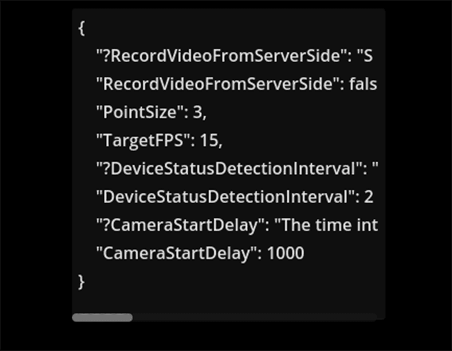
engine_config.json | Godot plugin | The settings for the engine. Can also be changed within the application. |
runtime_config.json | Godot plugin | The global settings for the application at run time. |
calibration_result.json | Calibration application | The extrinsic matrix of all devices tagged with the device's serial number, which is used to transform the point cloud from the device's coordinate system to the world coordinate system. |
system_config.json | Flowbit server library | The settings for the flowbit server for managing the system services. |
manager_config.json | Flowbit server library | The settings for the flowbit manager for managing the devices. |
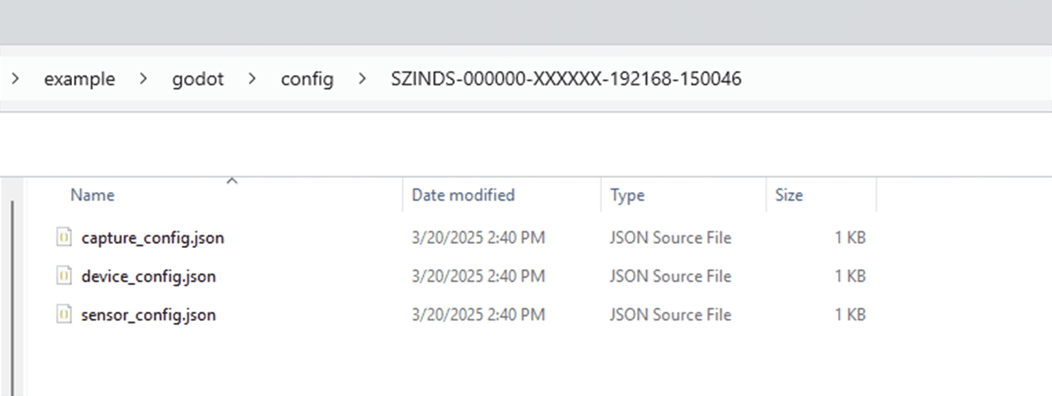
Each device's configuration files are stored in the config folder as
config/<device_sn>/capture_config.json,config/<device_sn>/device_config.json, andconfig/<device_sn>/sensor_config.json. They are automatically created by the flowbit server library after the devices are connected to the application.
The order to get the config folder is:
Try to open a
config.inifile in the project folder (running from manager or in editor) or in the same folder as the executable file (running from exported exe). If the file is found, the folder path containing the entry[Windows Settings][ConfigFolderPath](for Windows) or[Linux Settings][ConfigFolderPath](for Linux) is the config folder.
If the
config.inifile is not found, set the project folder as the config folderproject_folder/config.
Set the data folder
The data folder is used to store the data files, including the video files and the point cloud files. The data is saved with the following structure.
The order to get the data folder:
Try to open a
config.inifile in the project folder (running from manager or in editor) or in the same folder as the executable file (running from exported exe). If the file is found, the folder path containing the entry[Windows Settings][DataFolderPath](for Windows) or[Linux Settings][DataFolderPath](for Linux) is the data folder.
If the
config.inifile is not found, set the project folder as the data folderproject_folder/data.
Direct streaming
Open
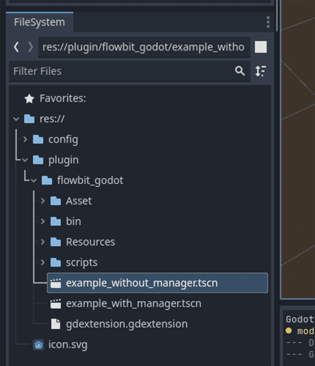
Peoject->Poject Settings->Application->Run, changeMain Scenetores://plugin/flowbitserver_godot/example_without_manager.tscnOpen
Peoject->Poject Settings, click to enableAdvanced Settings. Go toNative Extensions, clickPaths->Arrayto show the gdextension config. ChangeSizeto 1 and set the value of list0tores://plugin/flowbitserver_godot/gdextension.gdextension.In the
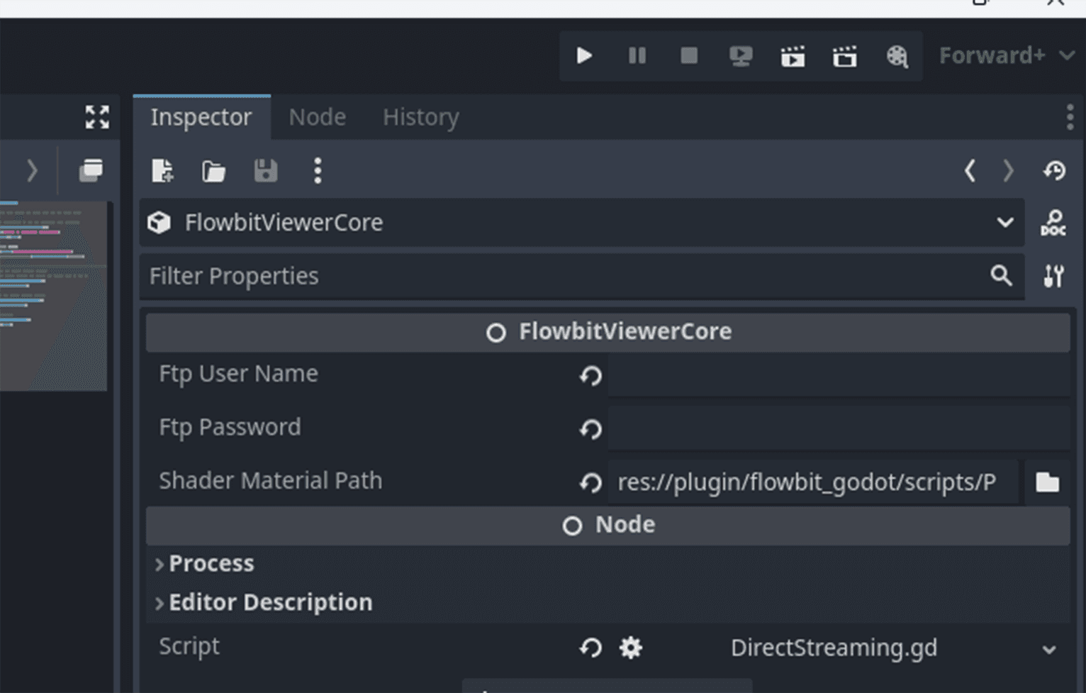
example_without_manager.tscnscene, click theFlowbitViewerCorenode, drag the shader material fileres://plugin/flowbitserver_godot/scripts/PointCloudRendering.materialtoShader Material Path. The FTP user name and password in the inspector are not needed for direct streaming.
In the node FlowbitViewerLivescenePanel , the inspector values are also not needed for direct streaming.
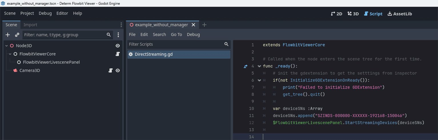
In the script attatched to the FlowbitViewerCore node, the InitializeGDExtensionOnReady function is called first to initialize the gdextension. Then the StartStreamingDevices function is called to start streaming devices.
Change the deviceSNs array to the device serial number you want to stream. Make sure the device profiles in config/<device_sn>/******.json exist. You can start the example_with_manager.tscn first to download the device profiles.
Press F5 to run the project. This will start the direct streaming of the target devices.
Fully functional example with manager enabled
Open
Peoject->Poject Settings->Application->Run, changeMain Scenetores://plugin/flowbitserver_godot/flowbitserver_godot/example_with_manager.tscnOpen
Peoject->Poject Settings, click to enableAdvanced Settings. Go toNative Extensions, clickPaths->Arrayto show the gdextension config. ChangeSizeto 1 and set the value of list0tores://plugin/flowbitserver_godot/gdextension.gdextension.
The primary node hierarchy and scripts are shown below.
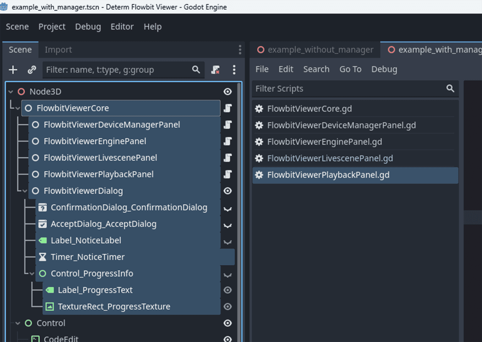
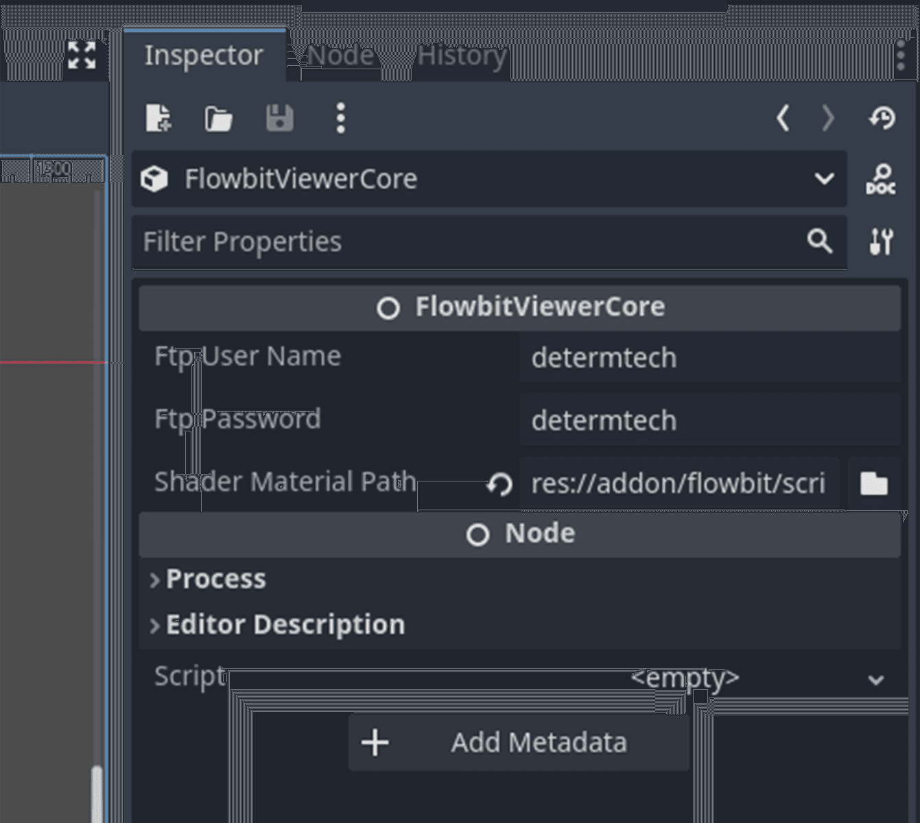
FlowbitViewerCore
Click FlowbitViewerCore node, and set the FTP user name and password in the inspector. Default values are both determtech . The FTP user name and password are used to download the device profiles from the server. Then drag the shader material file res://plugin/flowbitserver_godot/scripts/PointCloudRendering.material to Shader Material Path .
In the example project, it gets the config and data folder paths first, then starts the file system, system service, logging service in the constructor. These services are initialized in the constructor to make sure they are ready before the other nodes are initialized. InitializeGDExtensionOnReady() is used to get the settings from the inspector and initialize the gdextension.
Note: Global scene UI initialization relates to system info, version info, and author info. It should be called in
_init_scene(), after callingInitializeGDExtensionOnReady().
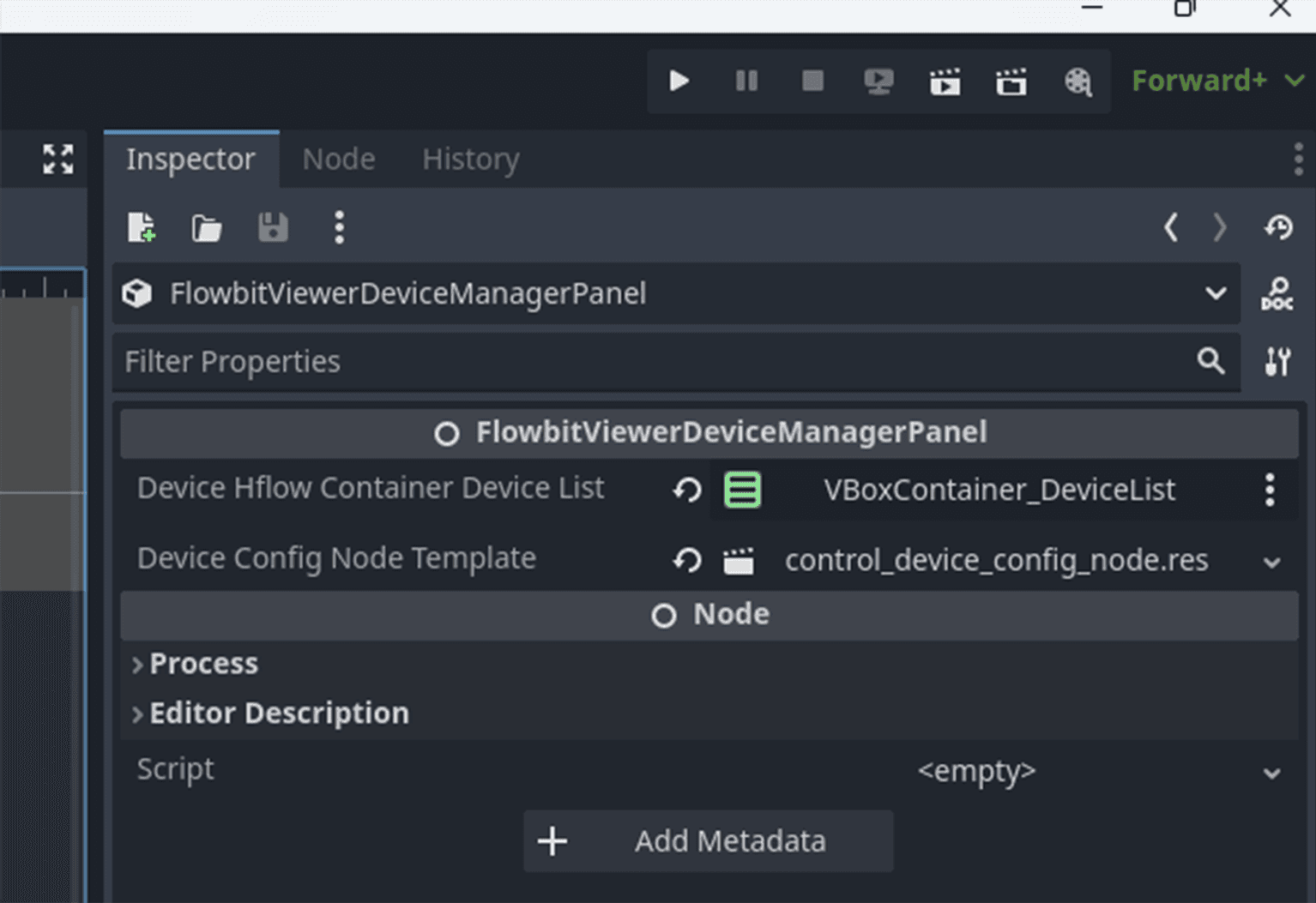
FlowbitViewerDeviceManagerPanel
Click FlowbitViewerDeviceManagerPanel node, drag VBoxContainer type device info list from the scene to the inspector. The container will list all devices in the UI. Drag res://plugin/flowbitserver_godot/Resources/control_device_config_node.res to the inspector. This is a template node to show each device's configuration.
This node maneges network device detection and device configuration. After starting the device manager service, it will detect all network devices in real-time and store the device info in the device list. The device list is a vector. The device info contains the device name, device type, device IP, device port, device status, and device configuration. The service works in background threads to detect devices and update the device list in real-time.
To show the device list in the UI, call the RefreshDeviceConfigNodes() function to create a DeviceConfigNode for each device and show it in the ScrollContainer. The DeviceConfigNode is dupilcated from the template control_device_config_node.res . In the example script attached to the FlowbitViewerDeviceManagerPanel node, the RefreshDeviceConfigNodes() function is called in the _process() function to refresh the device list in real-time.
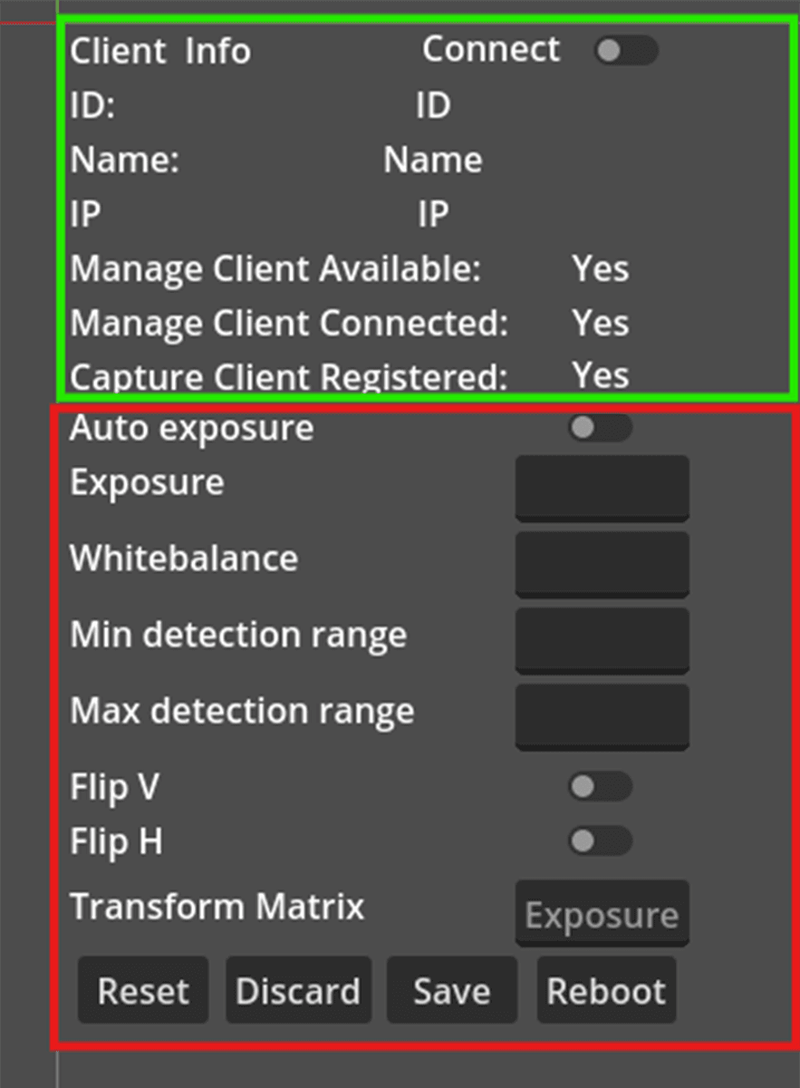
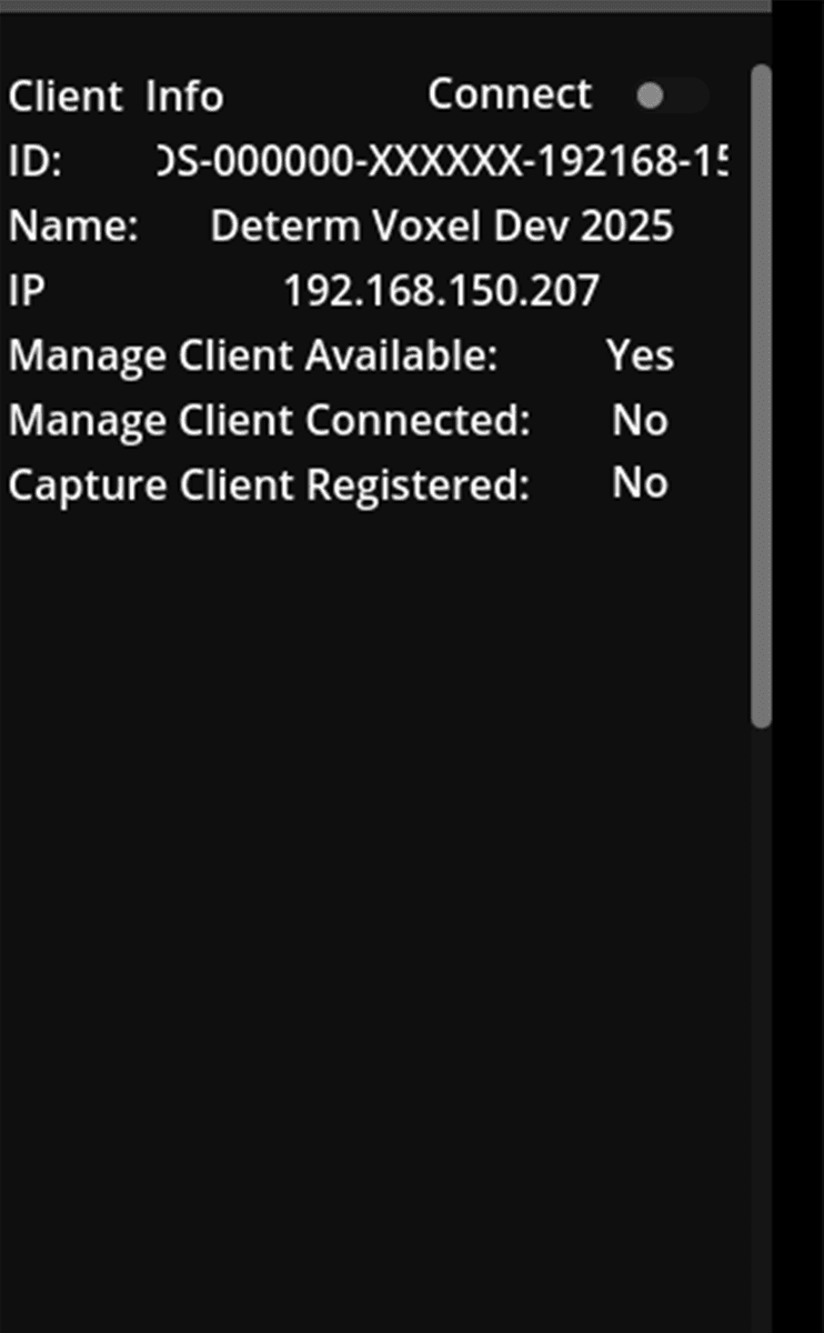
Users can connect/disconnect devices by clicking the connect/disconnect button in the UI. IF the device is not connected, only the basic config info is shown in the UI.
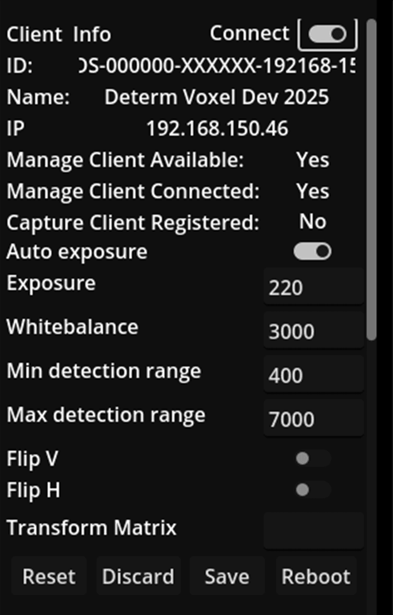
The basic config info is located in the upper part, including the device ID (serial number or SN), device name, device IP and device status.
After the device is connected, the device status will be updated and the device profiles will be downloaded to the config/<device SN> folder. If the device calibration file config/calibration_result.json exists, the device's extrinsic matrix is updated to the profiles by searching for the device SN in the calibration file. The device's extrinsic matrix is used to transform the point cloud from the device's coordinate system to the world coordinate system. If the file is not found or the the device SN if not found in the file, the device's extrinsic matrix is set to an identity matrix. In the UI, more device info will show in the UI, including exposure time, white balance, and other settings.
After the device is connected, users can also edit the device's configuration in the UI. The updated result is saved to the local profiles and also sent to the remote device.
If a device becomes unavailable, the device status will be updated to unavailable .
If the user stops the device manager service, all devices will be disconnected and the device list will be cleared.
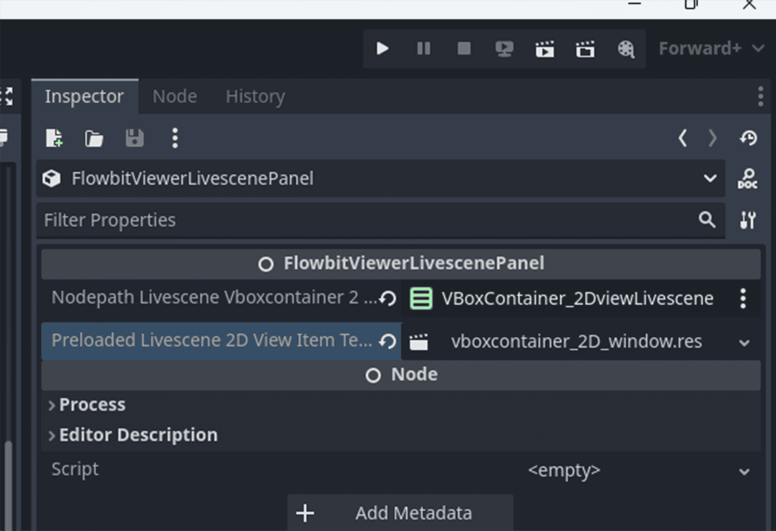
FlowbitViewerLivescenePanel
Click FlowbitViewerLivescenePanel node, drag VBoxContainer type 2D image window list holder from the scene to the inspector. The container will list the 2D RGB and depth image for all cameras. Drag res://plugin/flowbitserver_godot/Resources/vboxcontainer_2D_window.res to the inspector. This is a template node to show each device's 2D images.
This node controls the streaming and recording tasks. It can work with the 2D image window node to show the 2D images. The 2D image window node is created dynamically on starting the streaming task. If the 2D window list container and 2D window template are not set, the 2D image window will not be shown in the UI.
With this node, users can start streaming, stop streaming, start recording, stop recording.
Use the buttons Connect and Disconnect to connect or disconnect the server from the devices first. Only these connected devices can be streamed and recorded.
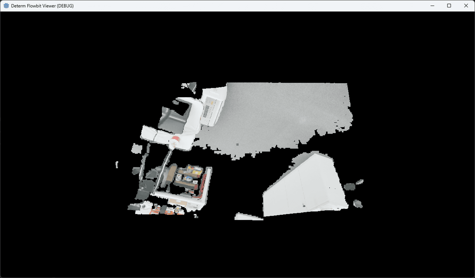
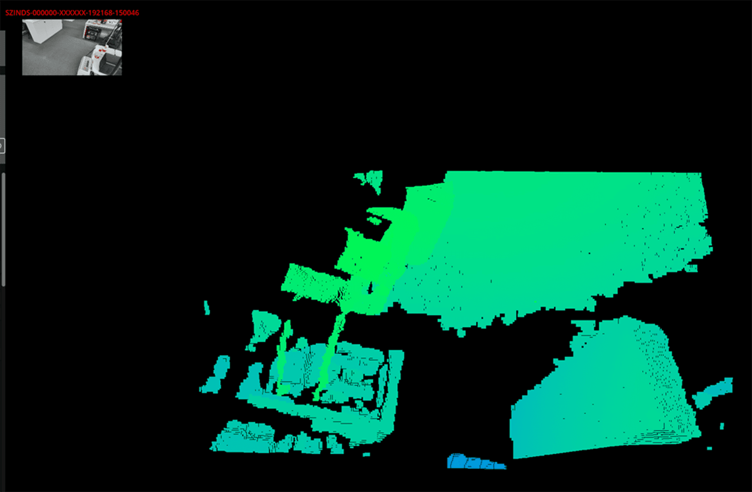
Press the buttons Stream and Stop on the Streaming panel to start or stop point cloud streaming after the server connects to the devices. If you press the Stream button, the Capture Client Registered message on the Client Info panel will turn to Yes. Then the point cloud streamed will be rendered in the window. Press the buttons Start recording and Stop recording to start or stop recording the point cloud. The server can only start the recording task after streaming. The server must stop the recording task first, then stop the streaming task.
After the recording task is started, the server will copy the device profiles to the data folder videos/<start time>/<device SN> and save a RGB and a depth image for current frame to the data folder. Each device has a folder in the data folder. If the video file is saved to the server side, the video file of each device is also saved to the data folder videos/<start time>/<device SN> .
When the point cloud is streaming and rendering in the window, use the WASDQE keys to move the viewpoint in the window, and use the mouse right button to rotate the viewpoint.
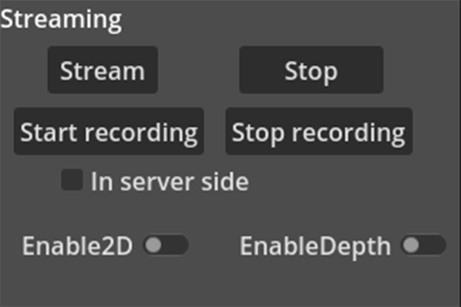
If In server side is toggled on, the server will save the recorded video files to the local data folder in the server side. If In server side is toggled off, the recorded video files are saved to the remote devices and must be downloaded to the local data folder before playing back.
On streaming, press the Enable 2D Window button to show the 2D image window in the UI. The 2D image window is created dynamically on starting the streaming task. The 2D image window is created for each device and shows the 2D RGB and depth image in real-time. Press the Enable Depth View button to show the depth view in the UI. It disables the point cloud color and only shows the depth value in the point cloud.
In script attached to the FlowbitViewerLivescenePanel node, please follow the steps to init.
Call the
InitializeGDExtensionOnReady()function to initialize the gdextension.Call the
_init_scene()function to initialize the UI related to live streaming.Call the
_set_callables()function to set the callable functions for the UI buttons. The callable functions are automatically called by the gdextension when internal status changes. This is used to change the UI status in real-time.
FlowbitViewerPlaybackPanel
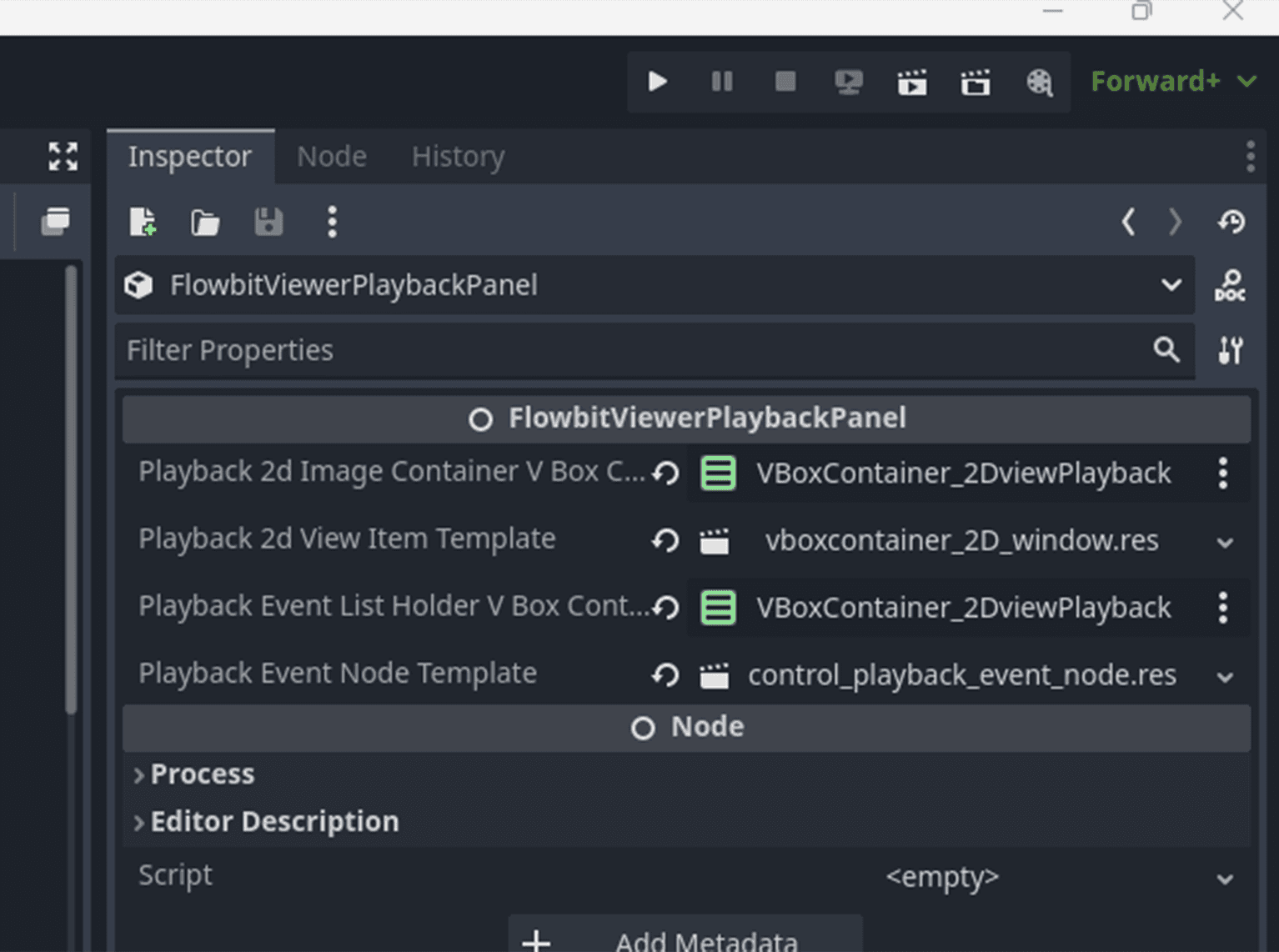
Click FlowbitViewerPlaybackPanel node, drag VBoxContainer type 2D image window list holder from the scene to the inspector. The container will list the 2D RGB and depth image for all cameras. Drag res://plugin/flowbitserver_godot/Resources/vboxcontainer_2D_window.res to the inspector. This is a template node to show each device's 2D images. Drag VBoxContainer type playback event list holder node from the scene to the inspector. This will show all playback events in the UI. Drag res://plugin/flowbitserver_godot/Resources/control_playback_event_node.res to the inspector. This is a template node to show each playback event.
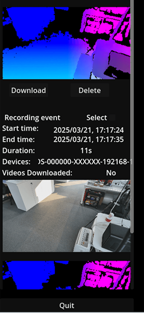
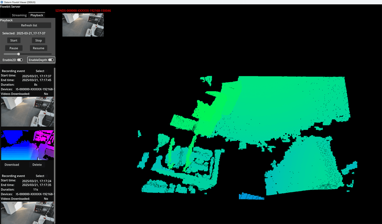
The UI is similar to the FlowbitViewerLivescenePanel node, but manages the playback events. It lists all playback events in the UI with PlaybackEventNode . Users can refresh the playback events by pressing the Refresh list button. It reads the playback events from the database in the local data folder and shows them in the UI. The playback event contains the event start time, event end time, event duration, device SN, and video file status. The video file status is No if the video file is not downloaded to the local data folder videos/<start time>/<device SN> . The video file status is Yes if the video file is in the local data folder. Press the Download button to download the video file to the local data folder, but the device must be connected first. The status will be updated to Yes after the video file is downloaded. By pressing the Delete button, the video file is deleted from the local data folder. The event will disappear from the list after refreshing the list.
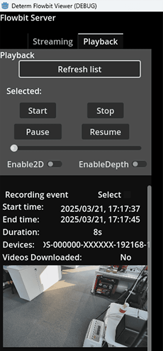
Users can select a playback event by toggling the Select button or double clicking the RGB or depth image. The selected playback event's start time is shown in the UI.
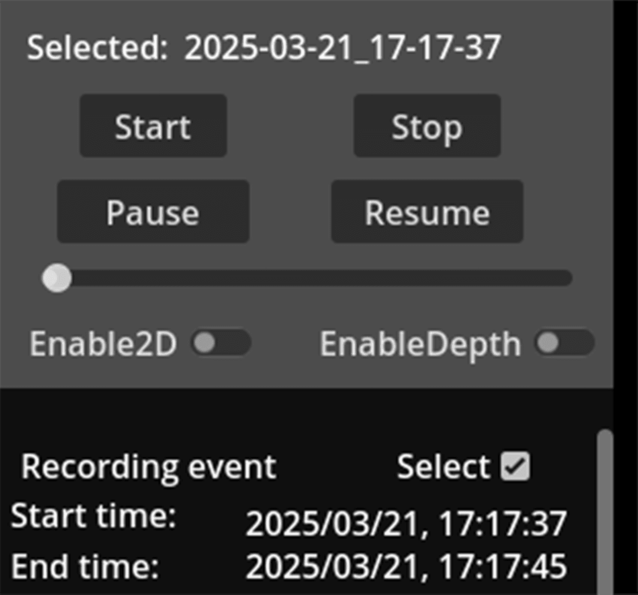
Users can press the Start button to start the playback task. The playback task will load the device profiles and the video file from the local data folder videos/<start time>/<device SN> for each device in the playback event. When the point cloud is streaming and rendering in the window, use the WASDQE keys to move the viewpoint in the window, and use the mouse right button to rotate the viewpoint. The playback task will stop if the video file is finished or the Stop button is pressed. The playback task can be paused by pressing the Pause button. The playback task can be resumed by pressing the Resume button. Users can also drag the slider to seek the playback event.
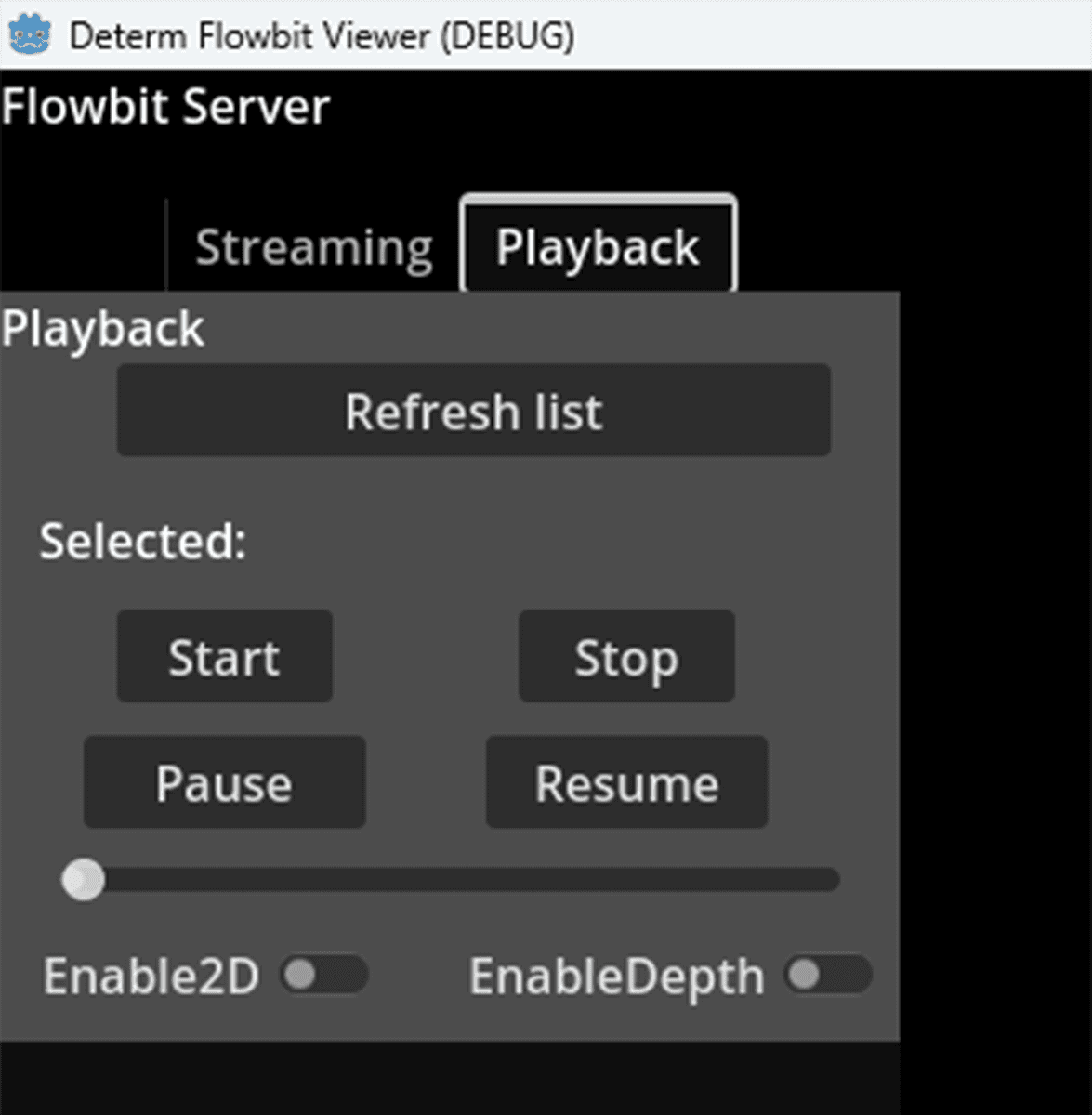
On pressing the Enable 2D Window button, the 2D image window is shown in the UI. The 2D image window is created dynamically on starting the playback task. The 2D image window is created for each device and shows the 2D RGB and depth image in real-time. On pressing the Enable Depth View button, the depth view is shown in the UI. It disables the point cloud color and only shows the depth value in the point cloud.
In the script attached to the FlowbitViewerPlaybackPanel node, please follow the steps to init.
Call the
InitializeGDExtensionOnReady()function to initialize the gdextension.Call the
_init_scene()function to initialize the UI related to playback.Call the
_set_callables()function to set the callable functions for the UI buttons. The callable functions are automatically called by the gdextension when internal status changes. This is used to change the UI status in real-time.
FlowbitViewerEnginePanel
Click FlowbitViewerEnginePanel node, drag a CodeEdit type node from the scene to the inspector. The code edit node will show the configurable engine info.
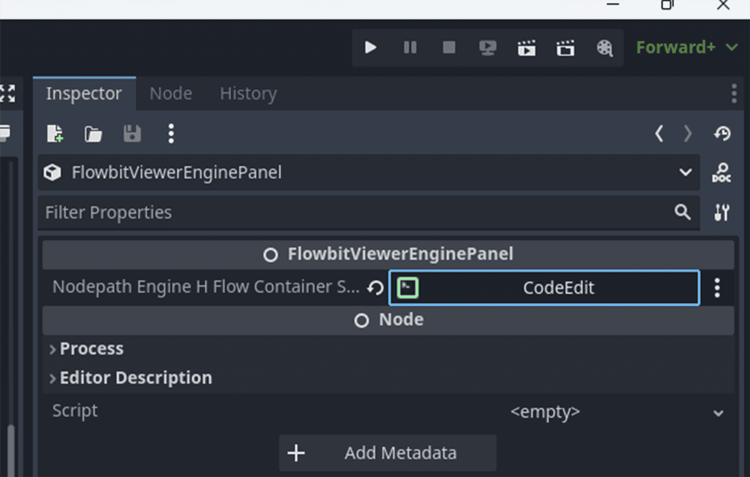
This node shows the engine config in the UI. Users can configure the engine config by editing, saving, and reloading the config. The engine config is saved to the local config folder config/engine_config.json . The engine config is loaded from the local config folder when the node is initialized.
FlowbitViewerDialog
This node contains the dialog component. It packs the dialog info and shows it in the UI. It connects to signals from the SignalEmitter node on initializing the dialog. Users can show accept, confirm, and notify dialog types by emitting signals from the SignalEmitter node. It also manages the progress dialog with text.
The signals are already connected in the gdextension. Users can emit signals to show accept, confirm, and notify dialog types, send system status to other nodes. But other nodes must connect to the signals on initialization.
SignalEmitter
The signal emitter node emits global signals from node to node. It is registered as a global singleton node in the project. SInce signals are defined in the SignalEmitter node, other nodes can connect to the signals on initialization.